Context Switch on the ARM Cortex-M0
I have written a simple round-robin scheduler (available on GitHub) for the ARM Cortex-M0 (ARMv6-M) CPU to understand the context switch mechanism. This article is a short summary of its principle.
The same approach is used by many RTOSes and is well described in The Definitive Guide to ARM® Cortex®-M0 and Cortex-M0+ Processors by Joseph Yiu.
Background
The processor has two separate stack pointer which can be accessed through banked
SP register: Main Stack Pointer (MSP) which is the default one after
startup and Process Stack Pointer (PSP) which can be optionally used.
The processor supports multiple modes:
- The default mode is the Privileged Thread Mode. It is possible to switch stack to PSP in this mode
- The Privileged mode can be switched to Unprivileged Thread Mode which has certain register and memory access restrictions
- Exceptions and interrupts are handled in the Handler Mode which uses the MSP stack.
In this application, tasks run in the Unprivileged Thread Mode with PSP and kernel runs in the Handler Mode with MSP. This allows stack separation between the kernel and tasks (which simplifies the context switch procedure) and prevents tasks from accessing important registers and affecting the kernel.
Context Switch
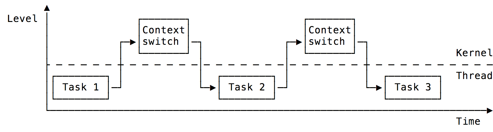
The context switch happens in an interrupt handler. Once an interrupt occurs,
the NVIC hardware automatically stacks an exception frame (registers
xPSR, PC, LR, r12 and r3-r0) onto the Process Stack (PSP)
and branches to the interrupt handler routine in Handler Mode (which uses the
Main Stack).
The context switch routine has to:
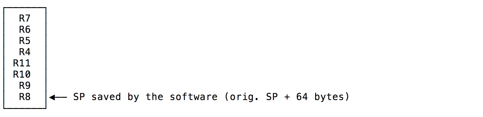
- Manually stack remaining registers
r4-r11on the Process Stack - Save current task’s PSP to memory
- Load next task’s stack pointer and assign it to PSP
- Manually unstack registers
r4-r11 - Call
bx 0xfffffffDwhich makes the processor switch to Unprivileged Handler Mode, unstack next task’s exception frame and continue on itsPC.
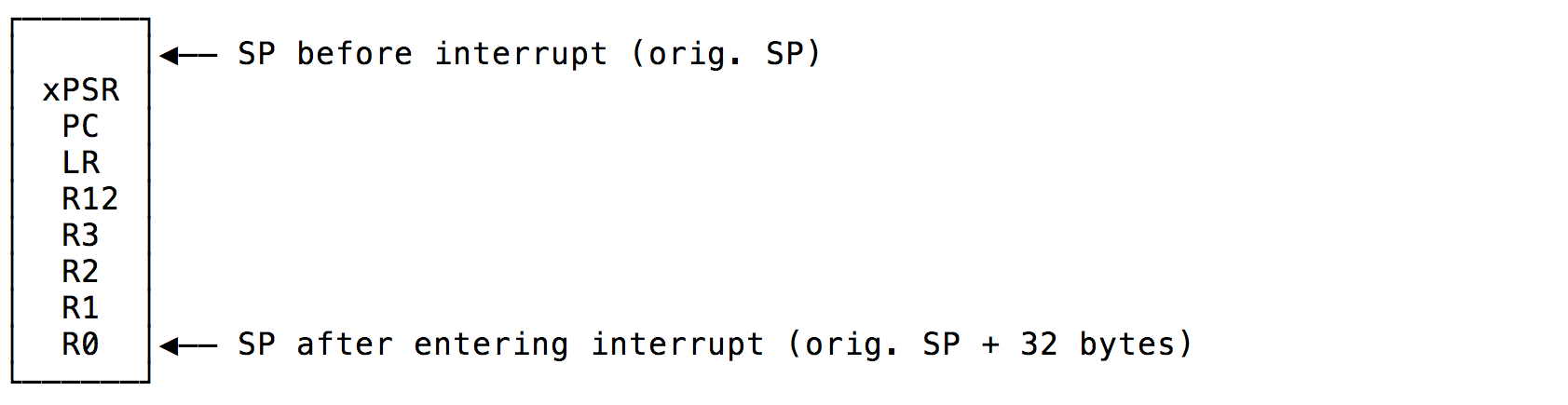
Exception frame saved by the NVIC hardware onto stack:
Registers saved by the software:
Performing the Context Switch
The context switch could be performed by the SysTick_Handler with a SysTick
timer configured to fire interrupts periodically:
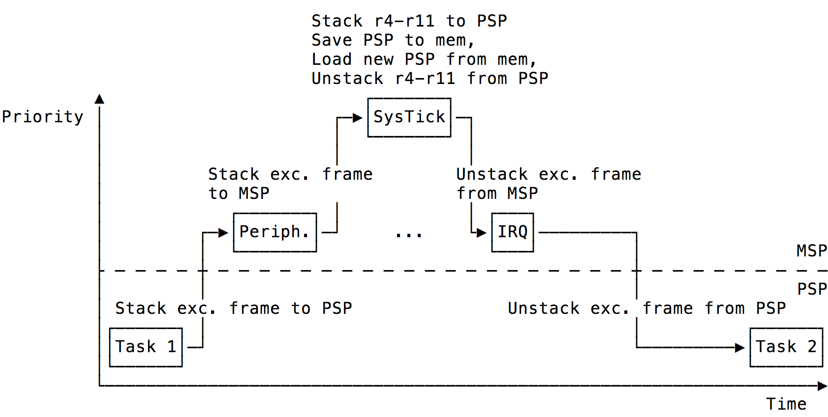
This approach would however not work with other interrupts (peripheral interrupt
for example). The SysTick_Handler would stack registers affected by the
peripheral IRQ handler and unstack task’s registers, resulting in undefined
behavior of both tasks and peripheral interrupt handler:
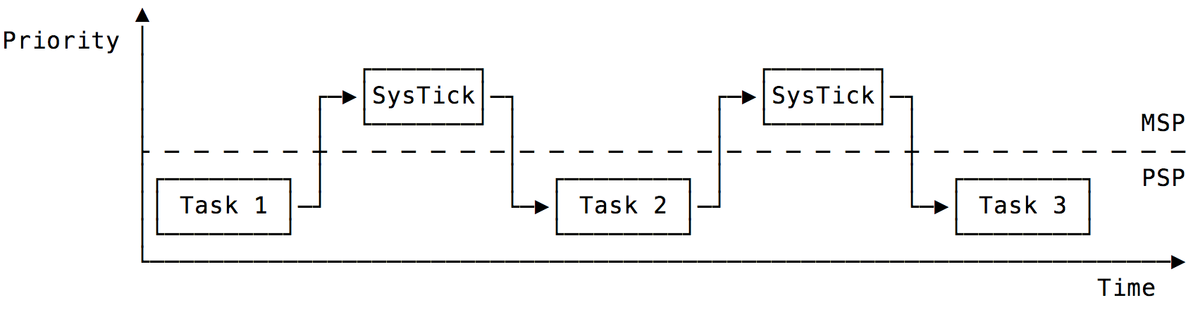
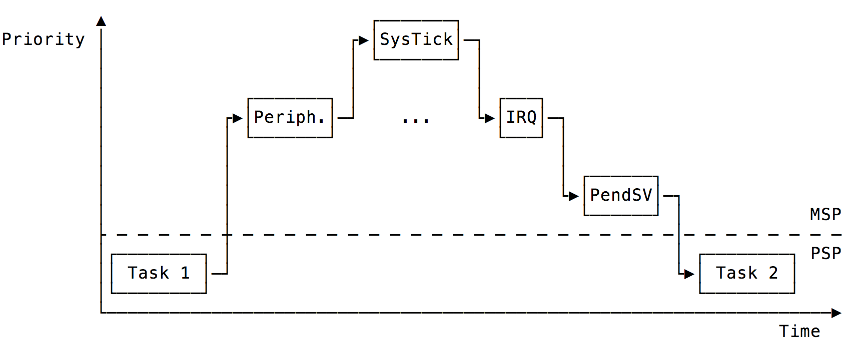
The solution is simple - the SysTick_Handler with the highest priority only selects the next task to be run and triggers PendSV interrupt. The PendSV_Handler with the lowest priority performs the actual context switch once all interrupt requests with higher priority have been handled:
The PendSV_Handler is written in pure assembly. The code relies on a fact
that the task’s stack pointer is the first element of the os_task_t
structure - the structure’s address corresponds to the address of its first
element according to C language specification.
Task Initialization
Each task is defined by its handler function and stack. The initialization phase of task’s stack must ensure that the first 64 bytes (16 words) form a valid exception frame. It is neccessary to store at least the default value of three registers:
xPSRto0x01000000(the defaul value)PCto the handler functionLRto a function to be called when the handler function finishes (otherwise the CPU would jump to invalid location, causing HardFault or undefined behavior)
The actual function os_task_init stores values for registers r0-r12 as
well for debugging purposes.
Startup
The startup phase has to configure SysTick and PendSV interrupt levels, initialize the SysTick timer to fire interrupts periodically and start the first task.
As the microcontroller starts in Privileged Thread Mode with Main Stack it is
neccessary to switch to Unprivileged mode with Process Stack. This is done by
writing to the CONTROL register followed by ISB instruction.
The os_start function is written without inline assembly thanks to functions and intrinsics provided by the CMSIS library.
Example
An example runs three tasks (which are switched every second). All tasks blink the onboard LED with different frequency.
The example can be run on STM32F030R8 Nucleo board and requires STM32Cube software pack which has to be present in the lib directory.
The provided Makefile requires GCC compiler and OpenOCD. See README for more information about compilation and flashing.
Compatibility
The SysTick timer and Privileged mode are optional features of the ARMv6-M architecture. They are however supported by vast majority of microcontrollers.
The code relies on standard CMSIS library by ARM which is usually distributed by microcontroller vendors. The library provides functions and intrinsics for accessing features of the ARM Cortex-M core.
Comments
The comments have been archived from Disqus.
I took a look through the code and saw that you handle the PendSv interrupt in assembly. Couldn't be used a naked interrupt and only the context switch to be made in assembly? I mean, some inline functions for context save/load.
Interesting article!
Hi, thank you and sorry for the delay. Yes, it could be also written as a naked interrupt (GCC:
__attribute__((naked))) with inline assembly and the__get_PSP()/__set_PSP()intrinsic functions provided by CMSIS.I usually tend to split the code into "pure C" and "pure assembly" functions as it is quite complicated to write a compiler-agnostic code with all the required function attributes and inline assembly.
Also, one has no control over the produced code and the compiler could in theory insert some instructions modifying registers before the inline assembly section (although this is not very likely).
The downside of my solution is that the assembly code has to access variables
os_curr_task/os_next_taskfrom os.c and that the structureos_task_tmust keep fieldspas its first element.Thank for your post, the picture were great!
Got a question about the final example with PendSV, where the execution flow looks like:
Task 1 -> Peripheral interrupt -> Systick -> IRQ -> PendSV -> Task2.
When Task 1 goes to the Peripheral interrupt, the exception frame gets pushed onto PSP. But what about R4-R11? Wouldn't this information get lost by the time PendSV tries to store Task 1's R4-R11 onto PSP? Is the Peripheral interrupt supposed to store R4-R11 onto the PSP?
Hi, good question!
If any interrupt service routine uses r4-r11 itself, it pushes them on stack "manually" on entry (the ISR code is responsible for that) and pops them on exit.
If no ISR uses r4-r11, the registers simply keep their content.
In both cases, r4-r11 contain Task 1's values when PendSV fires so the values stored are valid.
I see! Does the ISR push the registers onto MSP or PSP? I wanna say it's MSP since it's safer (e.g. what if the PSP was able to overflow).
The NVIC stacks exception frame to MSP (ISR is the user code which optionally stacks the registers which are not part of the exception frame already stacked by HW).
The only time when NVIC stacks to PSP is when an exception (e.g. interrupt) happens + the CPU is in a Thread mode (i.e. not in ISR) + the CPU has been configured to use PSP in the thread mode (this is not the default behavior but the code presented here does it as part of its initialization).